|
|
|

I will be controlling my 2005 display with the hobby kit controller provided by Light-O-Rama.
Below are pictures of the controller I built using a common electrical junction box.
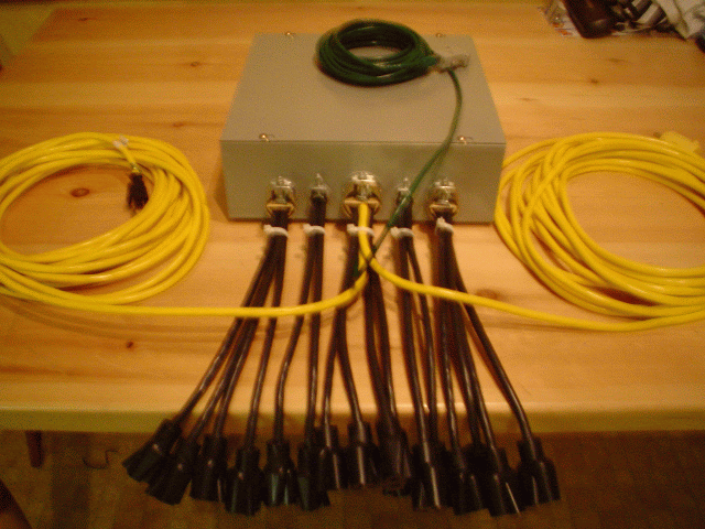
This is a picture of the whole controller. The yellow cords are the power IN cords, the 16 black cords are the power OUT-each 1 represents 1 channel; and the green cord is the CAT5 internet cord which allows the signal to be transfered from the computer to the controller.
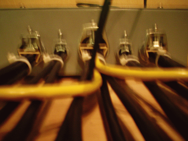
This photo shows how all of the cords enter the box.
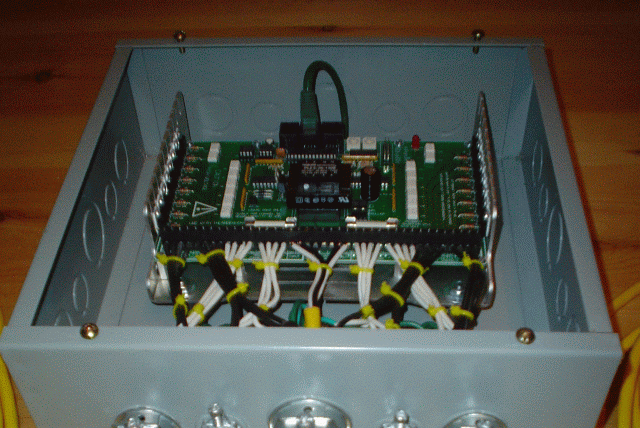
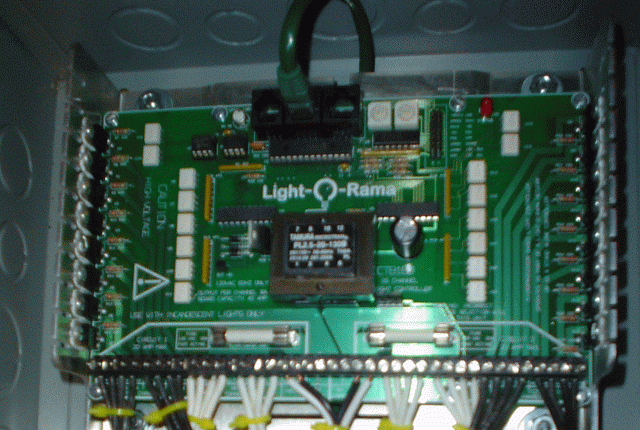
A good overall shot of the controller showing some of the inner components.
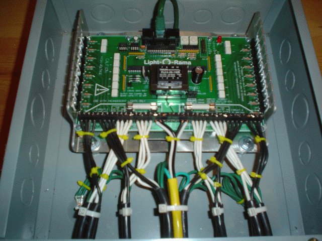
This shows the inner components, you can once again see the 2 yellow cords enter and attach to the controller (power IN), you can see all of the black cords connect (power OUT) and you can see the green Cat5 connecting at the top of the controller.
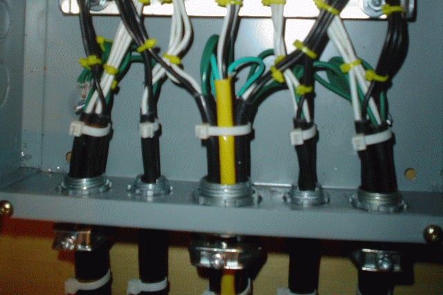
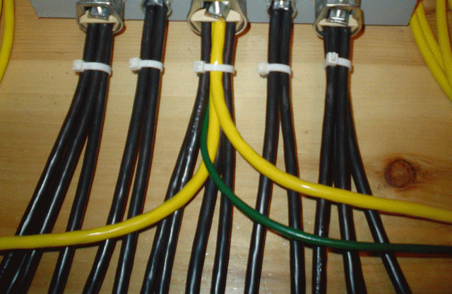
This is a good veiw of the wires entering through the box and shows the complete journey.
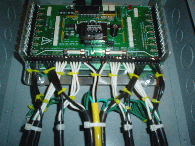
This is the last of the photos which shows another good view of the whole component system.
Questions? Comments? contact us
|
Read my DreamBook guestbook! Sign my DreamBook! |
|